 You can specify a single layer for all PlantManager data in a list or choose a separate layer
for each item.
You can specify a single layer for all PlantManager data in a list or choose a separate layer
for each item.|
Set
Options
|
The options window provides controls to help customise the drawing.

Three list types can be used to represent plant and finish information.
Once a list type has been defined and drawing objects created, it isn't possible to change to another list type.
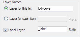
 You can specify a single layer for all PlantManager data in a list or choose a separate layer
for each item.
The 'Layer for list' option specifies a custom layer to be used for all objects in the (with an optional suffix for label objects or hatches).
The 'Layer for item' option results in layer names generated from each key name with a specified prefix. This option is not available for a Mix list as all included items are labeled as one Mtext or Multileader object.
Check the 'Label Layer' toggle to enter a suffix so that labels and leaders are created on a different layer from the plant boundaries, hatches or blocks.
List layer names are saved as part of the list definition. Changes made to names will update drawing items created from the list.
Select a slope if relevant in the slope factor drop down control. The value set will apply a multiplier to planting and finish areas. The value will be saved within the boundary object to apply the slope factor to any later spacing changes. You can change (or reset) the slope value for a previously assigned area by specifying an appropriate slope value and re labelling an existing label. The current slope (if set) is displayed at the bottom the palette.
Select a mode for representing spacing in the main dialog - either drawing units or quantities of plants per square metre. The latter setting is useful to maintain spacing regardless of drawing units.
Each list can have a unique label format.
Four preset formats are provided including variations on the quantity, key name and spacing fields. One preset uses the value of the 2nd field in the label (by default, the botanic name in a plant list).
When you change a preset or custom label setting, all labels in the drawing belonging to the current list are updated.
Check the Custom option and click the Define Label... button to specify a custom label. You can also access this option (to override a preset) by entering "ppl" at the command line or by clicking 'Customise Label' in the menu or ribbon.
A label quantity can be manually edited to override an automatically generated quantity value in the top two preset modes - Qty Key / Key (Qty) and will be used to generate schedule totals.
Note, this option is only available in Individual mode.
In all other cases, quantity values are extracted from the label's attached data with the quantity or other text data which may be included in the label, ignored. The audit function can be used to ensure the quantity value expressed in a label aligns with the value attached as data to the text or leader.
Drawing Annotation Styles

When checked you can use the drawing's default annotation styles for all PlantManager labels. Depending on the current setting (Leaders or Multileaders) the current Dimstyle or Multileader style will be used for labels. To modify the label style properties, edit it using the 'Dimstyle' or 'Mleaderstyle' command.
When unchecked, annotation styles will be created automatically using drawing units and plot scale settings to generate appropriate non annotative styles. PlantManager style names are prefixed with 'PM' and suffixed with the current plot scale.
In this mode, changes to the text height and style defined by the dimension or multileader style can be made using the Text Size and Style drop down box. Changes to these settings will both update labels using the style and redefine the current dimension or multileader style.

Container Sizes
Click the Container Size... button to open the Edit Container Sizes dialog (screenshot left) to change presets appearing in the drop-down lists of edit dialogs.

Image Libraries
Click to open a window to specify folders to be searched for display of images in the main dialog and the Data Browser.
Multiple directories can be specified. Images in format, .jpg, .bmp, .tif, and .png will be displayed if matching the botanic name (2nd field) of the selected entry.
You can display multiple images of the same entry with a unique suffix or prefix in the filename.

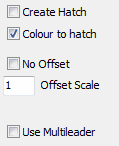
Create Hatch
When checked, a hatch object will be drawn in Create mode instead of a boundary polyline.
This setting doesn't preclude hatching inside a polyline which can be separately specified by checking the hatch option on the palette or main dialog. If a pattern hasn't been defined, the current default hatch pattern will be applied.
Colour to Hatch
When checked, colours assigned to polyline boundaries in 'Layer for list' mode will also be applied to associated hatches. This setting will be saved across drawings. The check box can be used to update older drawings as it scans hatches associated with each polyline boundary and changes colour to match the polyline.
Note this setting has no effect if a hatch is assigned to a plant or finish. Also it won't apply when 'Layer for item' is current as all boundaries and hatches will automatically be coloured ByLayer which can be changed in the layer palette.
Offset Control
Check the 'No Offset in Create mode' toggle to align polylines with boundary objects. The default setting is for an offset polyline to be created.When offset, the area of the enclosing boundaries are used to calculate quantities - not the offset boundary. In all other cases, the actual polyline area is used.
Use Multileaders
The default label type is a dimension leader with an associated Mtext entity. Check to draw Mulitleaders. Both label types can be used in the same drawing. The leader type setting will be applied as a default in new drawings.
While Multileaders provide flexibility including options for quickly adding leaders, the dimension leader is useful when hatching geometry it crosses as the leader line is not recognised as a hatch boundary.
Use the Load button to load PlantManager linetypes into the drawing. Once loaded, available linetypes are displayed in the drop down list. You can select and set a linetype for the current list. The linetype will be applied ByLayer in the case where a Layer for the list is specified.
Inadvertent changes to labels or boundaries can result in discrepancies which affect schedule accuracy.
The audit function scans the drawing for issues, fixes them where possible and prints a report to the screen and optionally to a file. The routine analyses plant and finish areas and labels as well as blocks and their labels. Run the function by typing 'pmaudit' at the command line
Areas and their labels
Issues identified and in some cases fixed by PMaudit include:

Orphaned Labels
Orphaned labels can also occur when labels are copied for other annotation purposes. The text value may have been edited however associated data is retrieved during scheduling or changes to a corresponding list. This situation can lead to inaccuracies with inflated quantities.
Orphaned labels can be disabled (but are not deleted) by checking the Remove PlantManager data option at the bottom of the audit report window. This will remove all data attached to the label to ensure it is not recognised during scheduling or list changes.
If the orphaned label was previously associated with a boundary or hatch and is not automatically re-linked during the audit process it can be manually linked using the PMLINK command.
At the command prompt, type 'PMLINK', select a label object first and then select a boundary polyline or hatch previously associated with the label. Re run the PMAUDIT command to update the label.
Generally the audit routine will ensure drawing data is consistent with that specified for all lists.
Sometimes this may not be desirable, for example, layers may have been manually changed to filter views of labels in viewports. In these circumstances, running the audit routine followed by an undo may be the best approach to identify issues which can be manually corrected.
Blocks and their labels
Blocks and their labels are checked to ensure they are on the layer specified for the list. If there are discrepancies, a choice is given to leave layers as found or change to match the lists' layer setting.
The audit routine can also be used to allow a block to be copied into a new list - where insertions are found matching the layer of the new list, an option is provided to assign blocks on the layer.

Click the hatch check box displayed in the palette or the main dialog to assign a pattern to the currently selected item - or the list in the case of a Mix of plants or seed.
Layer
You can specify a unique layer for hatches by including a suffix in the Layer edit box. Without a suffix, the hatch pattern is created on the same layer as specified for the item object.
Using the Reset all check box will apply the specified layer setting for all items in the same list as the selected item. In the case of mix lists, the layer of hatches in all other mix lists will be updated.
Scale and Angle
Set a scale and angle for the pattern if desired. A file located within the users support directory with a .pat extension will be sourced to generate the hatch patterns shown in this window. Additional patterns can be included by editing these files. (See the relevant customisation guides for AutoCAD / BricsCAD for more information)
Background Colour
Click the Background colour check box to inlcude a background fill for the specified hatch. A swatch to the left of the check box is enabled and can be clicked to open the colour selection dialog.
Transparency
Use the slider or type in a transparency value to be applied. Values can range from 1 to 90 with 90 being almost fully transparent and 1 opaque. A value of 0 will apply transparency ByLayer to the hatch object which is the default setting.
Changes to any of the above hatch settings will update all drawing objects previously defined with the pattern.